The TI-99/4A is normally clocked at 3.0 megahertz, i.e. 3 millions oscillations per second. However, the TMS9900 microprocessor should be able to tolerate upto 4.0 MHz. It is therefore tempting to crank up the clock speed and gain 33% in execution speed.
In fact, a later model of the TMS9900 was released, the TMS9900-40, that was meant to be clocked at 4 MHz. This one could be overclocked at 5 MHz or even 6 MHz with proper cooling. (Because CMOS gates only use current when then switch states, the faster you run a microprocessor, the more current it uses and the more it heats up. Not cooling it may end up destroying the chip).
Ideally, overclocking should not be permanent, as many program have timing loops that rely on a given console speed. This is the case for the floppy disk controller DSRs for instance. A good solution would be to have a small switch that lets you toggle speed. A software switch would be even better...
The clock signal inside the console is generated by the TIM9904 driver. This chip needs a signal 4 times as fast, so as to generate four different clock phases for the TMS9900 to use. It actually comes in two versions: the TIM9904 requires a 48 MHz crystal, and a tuning circuit to pick up the 12 MHz harmonic. The TIM9904A can use a 12 MHz crystal directly, with an optional tuning circuit for better stability.
TIM9904(A) |
This page describes several possible modifications.
Adding a 16 MHz crystal (for TIM9904A)
Tuning a 48 MHz crystal (for TIM9904)
Using oscillators (for both)
If your console has a TIM9904A, an obvious solution to overclock it is to replace the 12 MHz crystal with a 16 MHz one. The only difficulty is to find an appropriate crystal. It should be a serial-type crystal, with a 20-75 Ohm resistance and a minimum of 6 mW power dissipation (which is a LOT). The suggested stability is 0.005% from 0 to 70 `C.
Here is a diagram of the suggested modification:
TIM9904A |
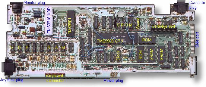
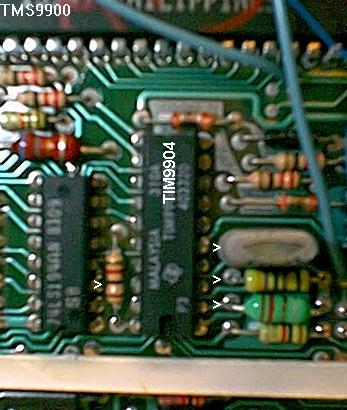
Open the console and locate the TIM9904 and its crystal. Here is a picture of the motherboard, and here is a blowup of the region when the TIM9904 is located. The crystal is easy to recognize: it's the tall metal container installed vertically near the TIM9904.
Note that I'm not 100% sure that both connections to the crystals need to be switched. It's quite possible that you could keep one common connection (say to XTAL1) and switch the other with a SPDT switch (single pole, dual terminal). I didn't either solutions.
In either case, it's very likely that flipping the switch will crash the computer, if only because there may be a moment when the poles are not connected to either terminals. So you must first decide whether you want 3 or 4 MHz, set the switch to the proper position, then power-up the console.
If your console has a TIM9904 (not A), it should have a 48 MHz crystal, with a resonnance circuitery tuned to pick up the 12 MHz harmonic. This raises the interesting possibility to change this tank circuit so as to pick the 16 MHz instead.
The resonnant frequency of the tuning circuit is calculated as:
Fosc =        1
       2*Pi*Sqrt(L*Ct)
L is the inductance of the coil.
Ct is the sum of the external capacitor C and the capacitance of the
printed
circuit board Cb.
To increase Fosc to 4 MHz, we need to decrease Ct by 0.75**2 = 0.56. This could be done by adding a second capacitor in series with the first one (as opposed to resistors, capacitors add up in parallel and decrease in series). A switch would let us bypass this second cap to obtain the original 3 MHz frequency.
TIM9904 |
The trick is to calculate the right value for the cap...
In my schematics book, L is indicated as .33 microHenry and C as 22 pF. If my calculations are correct, this means that, to pick 12 MHz, Ct should be 533 pF. Since the cap mounted on the motherboard is 22 pF, we can calculate that Cb is about 511 pF. This seems an awfull lot! Did I do a calculation mistake somewhere???
For Fosc = 16 MHz, we would need Ct to be 300 pF, which is impossible to achieve if the capacitance of the board is really that high.
Too bad: if it worked, it is quite possible that we could change speed "on the fly" without crashing the console. Maybe I did do a calculation mistake: could someone check my math, please?
Both the TIM9904 and the TIM9904A have the option of being driven by an external oscillator via the OSCIN pin, rather than with a crystal. In this case, the XTAL terminals should be connected to +5V and the tuning circuit should be replaced with a 130 Ohms resistor.
Since there are cheap 3-states oscillator with an output enable pin, I figured it should be possible to connect two of these to the OSCIN pin and to enable either one or the other with a CRU bit. I tested this solution and it does work! It has the advantage that the speed can be toggled by software, at any time during a program execution. For instance, before calling the floppy disk controller, or the RS232 card, which both are time-sensitive.
This modification also is fairly simple:
TIM9904 |
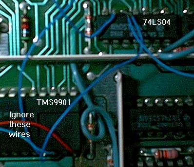
The TMS9901 interface controller is part of the console. Two of its pins are free for use: P0 (pin #38 ) and P1 (pin # 37). P0 is controlled by CRU bit 16 (address >0020), whereas P1 is controlled by CRU bit 17 (address >0022). Both pins are low upon reset, but the GROM routines switche P1 high during power-up. For this reason, I suggest you use P0.
The 74LS04 hex inverter is also part of the console: there are a few unused gates on this chip (U604).
The suggested oscillators are half-size, which makes easier to fit them under the motherboard metal case. Here is their pinouts, viewed from under. The OE pin is near the only corner the is not rounded. It should also be marked with a dot on top of the chip.
+---------,
| OE  Gnd |
|         |
|         |
| Vcc Out |
`---------'
To do this modification, first open your console. Refer to my console surgery page if necessary. Then locate the TIM9904. Here is a picture of the motherboard to help you.
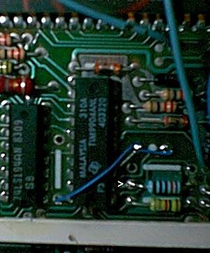
Here is a picture of the result. The newly installed resistor is marked with an arrowhead.
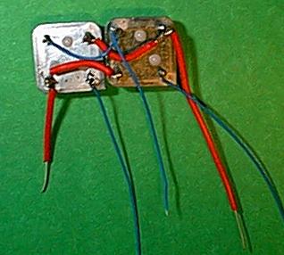
Here is a picture.
Here is a picture, the cardboard isn't in place yet.
Locate the TMS9901: it's the 40 pin chip, with no heat sink.
Which wire goes to which oscillator is up to you. If you used P0, the wire attached to pin #6 will select the default oscillator (i.e. the one that will be active upon power up). If you want a 3 MHz-by-default console, attach it to the 12 MHz oscillator. For a 4 MHz console, attach it to the 16 MHz oscillator. In either case, toggling the CRU bit will change speed.
If you selected P1 instead of P0, be aware that the console power-up routine toggle this bit. So in this case, it's the wire attach to pin #5 of the 74LS04 that should go to your default oscillator.
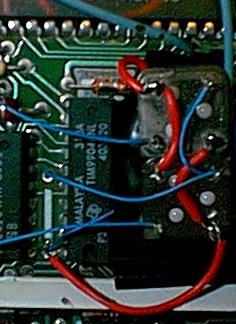
Here is a picture, in which I'm using P1 as the control pin. The reason being that P0 is used by another modification: please dissregard all these other wires.
Nothing could be easier:
* This routine selects the second oscillator * This routine goes back to the default oscillator |
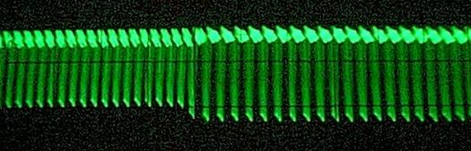
Here is a picture of the Phi3* signal captured by an ocilloscope during its transition from 4 MHz to 3 MHz. Observe how smooth the transition is (the black lines are markings on the scope's screen).